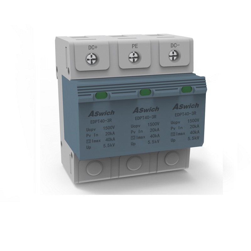
Because DC Surge Protection Devices for PV Installations must be designed to provide full exposure to the sunlight, they are highly vulnerable to the effects of lightning. The capacity of a PV array is directly related to its exposed surface area, so the potential impact of lightning events increases with system size. Where lighting occurrences are frequent, unprotected PV systems can suffer repeated and significant damage to key components. This results in substantial repair and replacement costs, system downtime and the loss of revenue. Properly designed, specified and installed surge protection devices (SPDs) minimize the potential impact of lightning events when used in conjunction with engineered lightning protection systems.

The Importance of SPDs
Long-term exposure to lower-magnitude transients deteriorates dielectric and insulation material in PV system equipment until there is a final breakdown. In addition, voltage transients may appear on measurement, control and communication circuits. These transients may appear to be erroneous signals or information, causing equipment to malfunction or shut down. The strategic placement of SPDs mitigates these issues because they function as shorting or clamping devices.
Technical Characteristics of SPDs
The most common SPD technology used in PV applications is the metal oxide varistor (MOV), which functions as a voltage-clamping device. Other SPD technologies include the silicon avalanche diode, controlled spark gaps, and gas discharge tubes. The latter two are switching devices that appear as short circuits or crowbars. Each technology has its own characteristics, making it more or less suitable for a specific application. Combinations of these devices can also be coordinated to provide more optimal characteristics than they offer individually.
An SPD must be able to change states quickly enough for the brief time a transient is present and to discharge the magnitude of the transient current without failing. The device must also minimize the voltage drop across the SPD circuit to protect the equipment it is connected to. Finally, SPD function should not interfere with the normal function of that circuit.
SPD operating characteristics are defined by several parameters that whoever is making the selection for the SPDs must understand. This subject requires more details that can be covered here, but the following are some parameters that should be considered: maximum continuous operating voltage, ac or dc application, nominal discharge current (defined by a magnitude and waveform), voltage-protection level (the terminal voltage that is present when the SPD is discharging a specific current) and temporary overvoltage (a continuous overvoltage that can be applied for a specific time without damaging the SPD).
SPDs using different component technologies can be placed in the same circuits. However, they must be selected with care to ensure energy coordination between them. The component technology with the higher discharge rating must discharge the greatest magnitude of the available transient current while the other component technology reduces the residual transient voltage to a lower magnitude as it discharges a lesser current.
The SPD must have an integral self-protecting device that disconnects it from the circuit should the device fail. To make this disconnection apparent, many SPDs display a flag that indicates its disconnect status. Indicating the SPD’s status via an integral auxiliary set of contacts is an enhanced feature that can provide a signal to a remote location. Another important product characteristic to consider is whether the SPD utilizes a finger-safe, removable module that allows a failed module to be easily replaced without tools or the need to de-energize the circuit.
